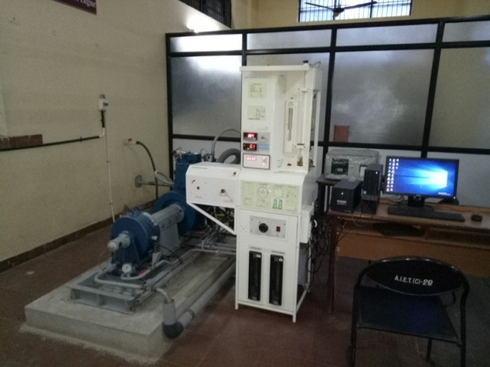
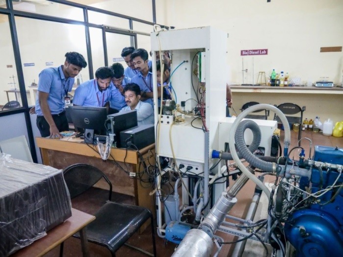
CRDI Engine Setup (For Bio Diesel and Alternative Fuels)
IC Engine research lab (ICERL) was established in the month of December 2017. The aim of this laboratory is to carry out research in the area of internal combustion engines with an objective of increasing fuel efficiency, emission control and engine durability and new technology development. ICERL is dedicated to introducing new technologies in IC engines. In the lab “Single cylinder 4 stroke computerized Common rail direct ignition (CRDI) variable compression ratio diesel engine” experimental was set up.
Objectives
- Research is focused on performance enhancement and reduction of emissions from I.C. Engines consuming alternative fuels
- The experimentation on performance characteristic, P-θ diagram and heat release
- Investigation of emission characteristic using 5 gas exhaust analyzer and smoke meter
- To inculcate research culture to gain knowledge in the field of alternative fuels.
- To help the UG, PG and Ph.D. research students to research in the field of alternate fuels.
Outcomes
- To produce as many as Research papers in reputed international journals.
- To find advanced ideas in the field of alternative fuels substitute to diesel.
Description
The setup consists of single-cylinder, four-stroke, CRDI VCR engine connected to the eddy current type dynamometer for loading. The compression ratio can be varied without stopping the engine and without altering the combustion chamber geometry by specially designed tilting cylinder block arrangement. In CRDI VCR fuel injection time, fuel injection angle, the ignition angle can be programmed with open ECU at each operating point based on RPM and mass air pressure. It helps in optimizing engine performance throughout its operating range. Air temp, coolant temp, mass air pressure and trigger sensor are connected to Open ECU which controls fuel flow, fuel injector and fuel pump. Set up is provided with necessary instruments for combustion pressure and crank‐angle measurements.
These signals are interfaced with a computer for pressure crankangle diagrams. Instruments are provided to interface airflow, fuel flow, temperatures and load measurements. The set up has a stand‐alone panel box consisting of air box, two fuel tanks for duel fuel test, manometer, fuel measuring unit, transmitters for air and fuel flow measurements, process indicator and hardware interface. Rotameter is providing for Engine cooling water flow measurement. A battery, starter and battery charger is provided for engine electric start arrangement. The setup enables the study of VCR engine performance for brake power, indicated power, frictional power, BMEP, IMEP, brake thermal efficiency, indicated thermal efficiency, Mechanical efficiency, volumetric efficiency, specific fuel consumption, A/F ratio, heat balance and combustion analysis. Labview based Engine Performance Analysis software package “Enginesoft” is provided for on line engine performance evaluation. Nira i7r software package is provided for programming open ECU of the engine.
The setup consists of single-cylinder, four-stroke, CRDI VCR engine connected to the eddy current type dynamometer for loading. The compression ratio can be varied without stopping the engine and without altering the combustion chamber geometry by specially designed tilting cylinder block arrangement. In CRDI VCR fuel injection time, fuel injection angle, the ignition angle can be programmed with open ECU at each operating point based on RPM and mass air pressure. Performance Analysis software package “Enginesoft” is provided for on line engine performance evaluation. Nira i7r software package is provided for programming open ECU of the engine.
Advanced Materials Lab(Materials Testing & Metallography)
Facility Available
Rapid Quenching Experimental Setup
The setup used for evaluation of Rapid cooling or quenching of apart from high temperature which can cause large thermal gradients and thus thermal stresses. If a phase transformation occurs simultaneously, phase transformation dilatations will add to the thermal dilatations and contribute to the internal stress distribution. The effect can be that local nonelastic deformations occur which will cause residual stresses when the part has attained its final temperature. The thermal and transformation processes are normally very rapid, and it is not possible to follow the stress buildup experimentally. Therefore computer modeling has been very important in increasing the understanding of the physical processes. The computed residual stresses can be verified experimentally. The experimental setup is very important to thermal analysis of the solid quenched specimens.
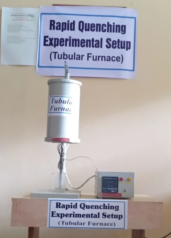
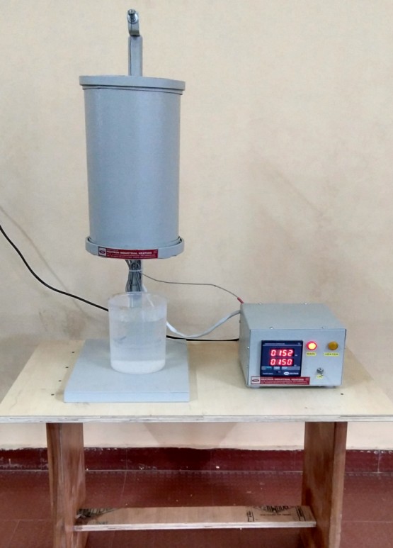
Figure: Rapid Quenching Setup
Pin On Disc Wear Testing Machine Machine
The Pin on disc wear testing machine used to study the wear properties of metals/alloys/composites/quenched specimens. The wear test can be conducted by applying a load at required disc speed (with a specified radius) for a particular period of time.
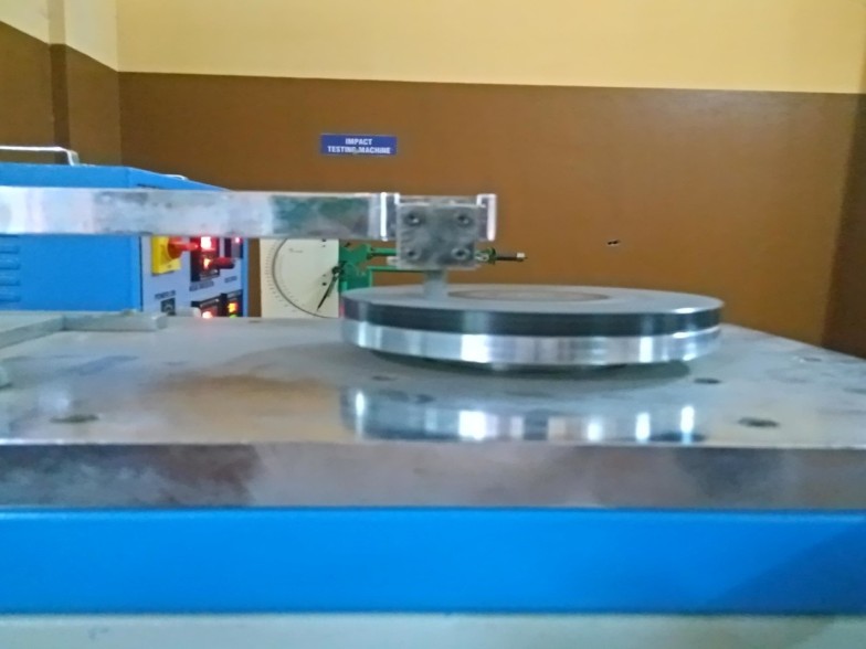
Figure: Pin On Disc Wear Testing Machine
Metallurgical Microscope
The Leica DM750 M is the ideal microscope for basic materials applications in an Industrial Lab or Material Science course. Its versatile stage and reflected light system work in combination to deliver high-quality images of the most demanding specimens.
The mechanical stage can be used for both transmitted and reflected light. It can be equipped with various specimen holders to accommodate mounted specimens of different diameters.
The unique Reflected light LED illuminator provides brightfield, polarized light, and oblique illumination. This allows you to work with many different specimens with the same microscope configuration.
Stands with both 4 and 5 position nosepiece allow for a full range of magnifications between 50x and 1000x.
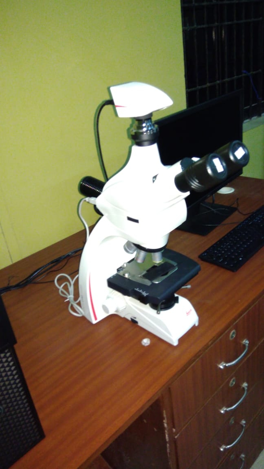
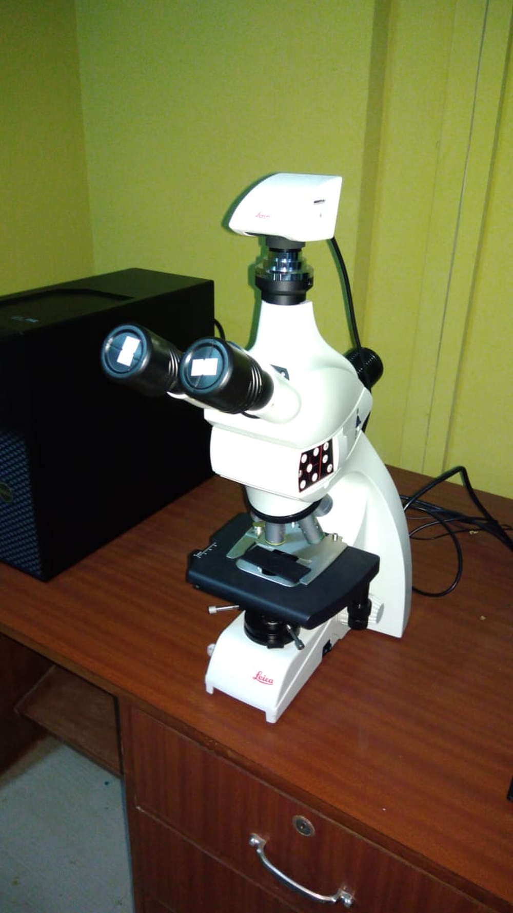
Figure: Metallurgical Microscope